Overview
Vertical wall type structures function as barriers whose purpose is to prevent a material from entering a certain space. Typical applications are embankment walls, bridge abutments, and as underground basement walls. Structural Engineers are responsible for the design of these structures. The loading acting on a retaining wall is generally due to the soil that is confined behind the wall. Various theories have been proposed in the literature, and it appears that all the theories predict similar loading results. In this chapter, we describe the Rankine theory that is fairly simple to apply. We present the governing equations for various design scenarios, and illustrate their application to typical retaining structures. The most critical concerns for retaining walls are ensuring stability with respect to sliding and overturning, and identifying the regions of positive and negative moment in the wall segments.
Introduction
Types of Retaining Walls
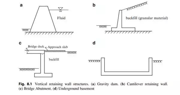
Vertical retaining wall structures are used to form a vertical barrier that retains a fluid or other material such as soil. Figure 8.1 illustrates different types of vertical retaining wall structures. They are constructed using unreinforced concrete for gravity walls and reinforced concrete for cantilever walls and bridge abutments. The base of the wall/footing is placed below the frost level. The material behind the wall is called backfill and is composed of granular material such as sand.
Gravity Walls
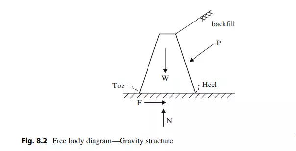
A free body diagram of a gravity structure is shown in Fig. 8.2. The force acting on the structure due to the back fill material is represented by P; the forces provided by the soil at the base are represented by the friction force F and the normal force N; lastly the weight of the structure is represented by W. The end points of the base are called the “toe” and the “heel.” We observe that P tends to overturn the wall about its toe and also to slide the structure in the horizontal direction. The overturning tendency is resisted by the gravity force W which has a counterbalancing moment about the toe. Sliding is resisted by the friction which is proportional to the normal force. Therefore, since both resisting mechanisms are due to gravity, this type of structure is called a “Gravity” structure.
Of critical concern are the sliding and overturning failure modes. The key design parameter is the length of the base. We need to select this parameter such that the factors of safety for sliding and overturning are sufficient to ensure global stability of the structure.
Cantilever Walls
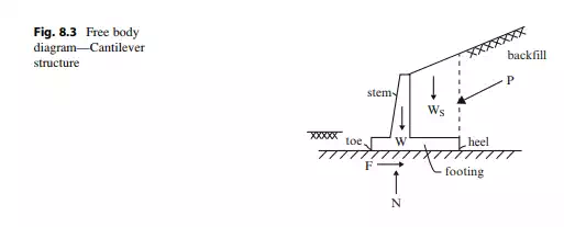
The amount of concrete required for a gravity type wall increases with height. Therefore, in order to minimize the concrete volume, the cantilever type retaining wall geometry shown in Fig. 8.3 is used. A portion of the concrete wall is removed and a “footing” extending out from both the heel and toe is added. This change has a stabilizing effect in that the weight of the backfill above the footing, represented by Ws, now contributes to the counterbalancing moment and also to the normal force. The wall stem segment of a cantilever wall carries load through bending action whereas the gravity wall carries load primarily through horizontal shear action. These behavior modes dictate the type of construction.
Cantilever retaining walls, such as shown in Fig. 8.4, are reinforced concrete structures; gravity type walls tend to be unreinforced concrete. The key design issue is the width of the footing. This parameter is controlled by the requirements on the factors of safety with respect to overturning about the toe and sliding of the wall.