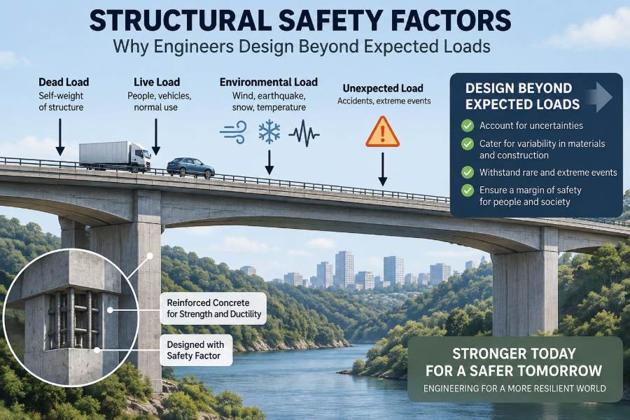

A balcony feels solid when you step onto it. A bridge deck carries traffic without drama. An office floor supports desks, people, partitions, and equipment while appearing almost motionless. That ordinary confidence is the visible result of many decisions made long before construction begins.
Engineers rarely design a member for one neat, predictable number called “the load.” Real structures face variation: materials differ slightly, occupants move, wind changes direction, workmanship has tolerances, and models simplify complicated behavior.
Structural safety factors are a disciplined response to that uncertainty. They are not arbitrary extra strength added because engineers are nervous, nor are they a substitute for understanding loads and behavior.
They provide margin between expected demand and unacceptable performance. To see why that margin matters, it helps to look behind the familiar phrase “designing for more than the expected load.”
🧱 The Basic Idea of Structural Safety
A structure is safe when it can perform its intended function for its intended life without unacceptable risk of collapse, excessive deformation, instability, or loss of usability. Collapse is the most severe concern, but it is not the only one.
A floor that sags enough to crack finishes, a bridge that vibrates uncomfortably, or a roof that leaks after excessive deflection may remain standing while still failing to meet its design purpose.
Safety factors create reserve capacity between what engineers reasonably expect and the point at which a specified limit is reached. The exact form of that reserve depends on the design method and the governing code.
📏 Expected Load Is Not a Single Exact Value
“Expected load” sounds precise, but most structural loads are estimates based on use, geometry, environmental data, and code-defined assumptions. A classroom floor may host students, furniture, equipment, and temporary concentrations of people in patterns no designer can predict exactly.
Even dead load, the permanent weight of the structure and fixed components, has uncertainty. Actual concrete density, slab thickness, façade details, services, and finishes can differ from early assumptions.
The question is therefore not simply, “Can this beam hold the average load?” It is, “Can it reliably perform under credible high-demand conditions, with realistic variation in resistance?”
⚖️ Load and Resistance Must Both Be Considered
Structural reliability depends on two sides of the same comparison: load effect and resistance. Load effect is the bending moment, shear, axial force, stress, or deflection caused by actions on the structure. Resistance is the capacity of the member, connection, or system to withstand that effect.
Both sides vary. Loads may be higher than anticipated, while resistance may be lower because of material variability, construction tolerances, deterioration, or a modeling assumption that proves less favorable in reality.
A useful conceptual condition is:
design resistance ≥ design load effect
Design values are deliberately adjusted values, not simply the nominal values first calculated from drawings or material test reports.
🧮 Two Common Languages for Safety Margins
Many engineers learn safety through either allowable-stress design or strength-based limit-state design. Their details differ, but both aim to maintain an appropriate margin against failure.
| Approach | General idea | Typical expression |
|---|---|---|
| Allowable-stress design | Keep calculated service-level stresses below an allowable fraction of a nominal strength. | Actual stress ≤ allowable stress |
| Strength or limit-state design | Increase load effects and reduce nominal resistance before comparison. | Factored load effect ≤ reduced design resistance |
Terminology and procedures vary by material and jurisdiction. A project must use the method required by its applicable building code and material standard rather than mixing equations from different systems.
🔢 Why Modern Codes Factor Loads Differently
Not all actions are equally uncertain or equally likely to reach their maximum at the same time. Permanent self-weight is usually more predictable than occupancy loading. Wind, snow, earthquake effects, temperature movement, and fluid pressures have their own patterns of uncertainty.
Load combinations reflect this reality. They combine actions in ways intended to represent credible severe conditions, without assuming that every possible load reaches its individual maximum simultaneously.
This is why a design calculation may show several combinations rather than one total load. The controlling case for a column may differ from the controlling case for a roof beam or foundation.
🏠 Dead Loads Are Steady but Not Perfectly Known
Dead loads include the weight of structural members, slabs, roofing, cladding, fixed partitions, and permanently attached services. They are often treated as stable over time, which makes them relatively predictable.
But “relatively” matters. A thicker-than-assumed topping, heavier façade panel, added ceiling system, or later renovation can increase permanent gravity demand. For long spans or heavily loaded columns, those additions can be consequential.
Good practice is to maintain a clear load path and document assumed superimposed dead loads so future design teams can assess changes rather than guess.
👥 Live Loads Move, Gather, and Change with Use
Live loads are imposed by people, furniture, movable equipment, stored goods, and activities. Unlike dead loads, they can shift across a floor and concentrate near a support, opening, or aisle.
A residential room, library stack area, warehouse, parking deck, and assembly space do not have the same loading expectations. Changing a room’s use without reviewing the structure can therefore be more serious than it appears.
Code live loads are not promises that no higher local load will ever occur. They are standardized design provisions tied to occupancy and use assumptions. Unusual machinery, storage, crowds, or temporary construction loads may require a project-specific assessment.
🌬️ Environmental Loads Bring Rare but Real Demands
Wind, snow, rain ponding, flood, ice, thermal movement, and earthquake effects can govern a design even when they occur infrequently. Their intensity depends on site conditions, building geometry, exposure, elevation, and structural response.
For example, wind does not apply uniform pressure to every surface. Corners, edges, roof zones, openings, and changes in shape can produce localized pressures or suctions that control connection design.
Safety provisions for environmental actions are rooted in hazard models and code rules, but they do not eliminate uncertainty. Site-specific conditions and correct detailing remain essential.
🌎 Earthquake Design Is About Controlled Behavior
Seismic design is often misunderstood as designing a building so strong that it remains completely unchanged during any earthquake. In many systems, the intended objective is more nuanced: prevent collapse in severe shaking while allowing controlled, repairable damage under defined conditions.
This depends on ductility, the ability to deform substantially without sudden loss of strength. Reinforcement detailing, connection configuration, confinement, and a continuous load path are as important as member size.
A brittle member can have substantial nominal strength yet perform poorly if it cannot redistribute force after cracking or yielding. Safety factors alone cannot correct a poor failure mechanism.
🧪 Material Strength Is Measured in Samples, Not Guarantees
Steel, concrete, timber, masonry, and engineered wood products have specified properties, but real materials exhibit natural variation. Test specimens represent production under prescribed conditions; an installed structure includes fabrication, placement, curing, moisture, and environmental effects.
Concrete strength, for instance, develops through a mix design and curing process, while reinforcement must be correctly placed and developed. Timber properties vary with species, grade, grain direction, knots, moisture, and duration of loading.
Design standards account for these realities by using defined characteristic or nominal strengths and appropriate resistance adjustments. A published strength is not a license to assume every piece performs identically.
📐 Models Simplify the Physical Structure
Analysis models convert a three-dimensional building into supports, members, loads, stiffnesses, and boundary conditions. This is necessary, but every model contains assumptions.
A connection drawn as pinned may have some rotational stiffness. A support assumed fixed may settle or rotate. A slab may distribute force across multiple beams more than a simple model predicts, or less if cracking and openings alter its stiffness.
Engineers use judgment, conservative assumptions where appropriate, and increasingly sophisticated analysis tools. Yet software can only calculate the model supplied; it cannot independently verify that the modeled behavior matches the built structure.
🔗 Load Paths Matter More Than Strong Isolated Members
Every load needs a continuous route to the ground. Roof loads pass through decking, joists, beams, columns or walls, connections, and foundations into supporting soil. Lateral loads follow a different but equally vital route through diaphragms, collectors, frames, walls, bracing, and foundations.
A strong beam does not help if its connection fails first. Likewise, a robust shear wall cannot stabilize a building if floor diaphragms cannot transfer lateral force into it.
When reviewing a design, trace the load path in both directions: from the point of loading to the foundation, and from the foundation back to every element that must participate.
🧷 Connections Often Control the Design
Bolts, welds, anchors, reinforcing development lengths, bearing areas, and screws may look secondary beside large beams and columns. In reality, they are often the locations where forces change direction, concentrate, or transfer between materials.
Connection design must address force magnitude, eccentricity, stiffness, ductility, installation access, corrosion exposure, and possible construction sequence. A connection that works on paper but cannot be inspected or tightened reliably is not a complete solution.
Detailing is therefore a safety tool. Clear drawings and constructible connections help ensure that the intended capacity becomes actual capacity.
📉 Failure Is Not Always a Sudden Break
Some structural failures are abrupt, such as brittle fracture or a connection rupture. Others develop through excessive deflection, fatigue cracking, corrosion, settlement, buckling, or progressive overstress.
Buckling is especially instructive. A slender compression member may be made from high-strength material but lose stability at a load far below the material’s crushing strength. Its geometry, end restraint, imperfections, and lateral bracing govern the result.
Design checks must match plausible failure modes. Checking only material stress can miss instability, local crushing, punching shear, vibration, or connection failure.
🌀 Stability Requires Its Own Margin
Structures can lose equilibrium or change shape dramatically even when individual components have not reached their nominal material strength. Examples include a column buckling, a frame swaying excessively, a retaining wall sliding, or an uplifted roof connection pulling free.
Second-order effects add another layer. As a loaded column or frame deflects, the displaced load creates additional moment. This P-Delta behavior can amplify drift and demand, especially in slender or flexible systems.
Bracing, diaphragm continuity, restraint, foundation anchorage, and realistic stiffness assumptions are central to stability. Extra beam strength alone may not address a system-level instability problem.
🧰 Serviceability Protects Function and Confidence
Strength provisions primarily address safety against serious failure. Serviceability checks address how a structure behaves in normal use: deflection, crack width, vibration, settlement, drift, water ponding, and movement of finishes.
Consider a long-span floor that is strong enough but vibrates noticeably when people walk across it. It may satisfy a strength check and still be unsuitable for a laboratory, office, residential space, or sensitive equipment.
Serviceability criteria are often less universal than strength provisions because acceptable performance depends on occupancy, finishes, perception, and function. Early coordination with the project team is more effective than attempting to hide a serviceability problem later.
⏳ Time Changes Both Loads and Capacity
Structures are designed for a service life, not merely for opening day. Over time, concrete can creep and shrink, timber can change moisture content, steel can corrode, protective coatings can degrade, and foundations can settle.
Repeated loading can also matter. A bridge detail or crane-support component may experience many stress cycles. Fatigue design considers crack initiation and growth under repeated stress ranges, which is different from a single maximum-load check.
Durability measures such as drainage, cover to reinforcement, corrosion protection, movement joints, access for inspection, and material selection preserve the assumptions behind original capacity.
🔍 Construction Quality Is Part of Structural Resistance
A calculation establishes what a properly built detail should achieve. Construction quality determines whether it does. Incorrect reinforcing placement, missing bolts, poor weld procedure, inadequate concrete consolidation, damaged members, or unauthorized field changes can reduce capacity.
Inspection and testing provide checkpoints, not ceremonial paperwork. Their purpose is to verify critical features when correction is still possible.
- Confirm member sizes, grades, and orientations.
- Inspect reinforcement, anchors, and embedded items before concealment.
- Review welds, bolting, grouting, and connection fit-up as required.
- Record approved changes and communicate them to the design team.
Inspection scope varies by project and local requirements, but the principle is consistent: safety margin should not be consumed by avoidable execution errors.
🚧 Construction Stages Can Be More Demanding Than Final Use
During construction, a structure may be incomplete, temporarily braced, or loaded in ways that do not occur in the finished building. Fresh concrete, stacked materials, equipment, formwork, partial diaphragms, and unbraced steel frames can create critical temporary conditions.
For example, a completed composite floor may be stable, while the steel beams supporting wet concrete before composite action develops require separate checks. Removing temporary bracing too early can change the structural system abruptly.
Temporary works deserve engineered planning, clear responsibility, and communication between contractor and designer where the permanent design depends on a particular erection sequence.
🏢 A Change of Use Can Quietly Erase Margin
Safety factors do not create unlimited capacity for future alterations. A light office converted to archive storage, a roof used for equipment, or a retail area fitted with heavy displays can impose loads beyond the original assumptions.
Openings cut into slabs and walls can interrupt reinforcement, diaphragms, or load paths. Removing a partition may also remove an element that had unintentionally become a brace or support.
Before altering use, loading, structure, or major building services, obtain a competent structural review. The relevant question is not whether the change “looks minor,” but whether it changes demand, stiffness, support conditions, or force transfer.
🧠 Reliability Is About Probability, Not Invincibility
Structural design manages risk; it does not promise that failure is impossible under every imaginable event. A design basis selects levels of hazard and performance consistent with codes, intended use, and accepted societal risk.
Very rare, extreme, or unforeseen events can exceed those assumptions. This is why robust detailing, redundancy, inspection, maintenance, emergency planning, and sound judgment remain valuable alongside code compliance.
Safety factors reduce the likelihood of unacceptable outcomes; they do not turn a structure into an indestructible object.
🕸️ Redundancy Gives Structures Alternative Paths
A redundant system has more than one practical route for carrying load. If one member or connection is damaged, other elements may redistribute some force rather than allowing an immediate disproportionate collapse.
Continuous framing, tied floors and walls, multiple load paths, and ductile connections can improve robustness. The benefit depends on the system’s ability to deform and redistribute force without triggering another weak link.
Redundancy must be analyzed thoughtfully. Adding members does not automatically make a structure safer if force attracts into a stiff element, connections remain weak, or the added complexity makes construction errors more likely.
🧩 Safety Factors Cannot Fix Bad Decisions
Increasing member size may help with strength, but it cannot reliably compensate for a missing load path, poor drainage, inadequate fire protection, incompatible materials, or an unverified foundation condition.
Similarly, applying a larger factor to a flawed analysis model gives a more conservative answer to the wrong problem. The most valuable safety decision may be correcting the structural concept before refining calculations.
Early choices about spans, column layout, lateral system, foundation strategy, regularity, and drainage often have more influence on reliability than small adjustments made near the end of design.
💰 Why “More Material” Is Not Always Safer
Oversizing everything can increase cost, embodied carbon, foundation loads, and construction difficulty. It can also create unintended behavior, such as a very stiff element attracting larger seismic forces or a heavy roof increasing lateral demand.
Efficient safety comes from understanding mechanisms, not simply maximizing dimensions. A well-proportioned braced frame, properly detailed connection, or continuous tie can provide more useful reliability than indiscriminate mass.
Codes aim for consistent safety across different materials and systems, while allowing engineers to optimize a solution for the project’s actual demands.
🧾 Codes Set a Minimum Framework, Not a Complete Conversation
Building codes and referenced standards provide the shared baseline for loads, combinations, material behavior, detailing, and inspection. They are essential tools because they capture accumulated engineering practice and establish enforceable expectations.
However, codes cannot describe every site condition or unusual use. Existing structures, unusual geometry, innovative materials, extreme exposure, and alterations often require additional investigation and professional judgment.
Engineers must also verify which edition and local amendments apply. Using a familiar provision from another jurisdiction or an outdated standard can produce a design that is technically polished but not appropriate for the project.
🗂️ A Practical Checklist for Reading a Design
Students and early-career professionals can strengthen their reviews by asking a sequence of simple questions before focusing on detailed arithmetic.
- What loads act, and which combinations are credible?
- Where does each load go, including lateral and uplift forces?
- What failure modes could govern each member and connection?
- Which assumptions are uncertain or sensitive?
- Are strength, stability, serviceability, and durability all addressed?
- Can the detail be built, inspected, maintained, and altered safely?
This checklist does not replace code calculations. It helps reveal omissions that a spreadsheet, however accurate, may not expose.
⚠️ Common Misunderstandings About Design Margin
One misconception is that a safety factor means a structure can safely carry that exact multiple of every load. In reality, different load types, combinations, limit states, and material provisions interact; no single multiplier describes the entire structure.
Another is that visible damage always means imminent collapse, or that no visible damage means no risk. Cracking, deflection, corrosion staining, and vibration need evaluation in context. Some are expected behaviors; others indicate a loss of capacity or durability.
A third misconception is that compliance removes the need for maintenance. Design assumptions include drainage, protection, use limitations, and periodic attention over the structure’s life.
🛠️ What Owners and Users Can Do
Non-engineers play a real part in preserving structural safety. Keep drains and expansion joints functioning, report new cracks or unusual movement, avoid unreviewed heavy storage, and do not modify structural components without assessment.
Warning signs deserve prompt professional attention when they are sudden, widening, widespread, associated with water damage or corrosion, or accompanied by unusual sounds, sticking doors, settlement, or noticeable change in floor level.
Observation is not diagnosis. The appropriate response is to document conditions and engage a qualified professional, especially where public occupancy or critical operations are involved.
🎓 What Students Should Carry Into Practice
Safety factors are often introduced as numbers in equations. In practice, they represent a broader discipline: recognize uncertainty, identify credible failure modes, use appropriate code provisions, and communicate assumptions clearly.
Develop the habit of sketching load paths, checking units, questioning boundary conditions, and looking at details as carefully as member calculations. Learn the limits of software outputs and seek review from experienced engineers.
The best calculations are not merely correct; they correspond to a structure that can be built, inspected, used, and maintained as intended.
🏗️ The Core Principle: Reliable Performance Despite Uncertainty
Engineers design beyond expected loads because expected conditions are not the same as guaranteed conditions. Loads vary, materials vary, models simplify, construction introduces tolerances, and time changes the structure.
Safety factors, load combinations, resistance reductions, ductile detailing, stability checks, serviceability limits, inspection, and maintenance work together as a system of protection. Each addresses a different way real structures can depart from ideal assumptions.
The goal is neither wasteful overdesign nor blind confidence in a single calculation. It is a structure with a well-understood path to reliable performance under the conditions it is reasonably expected to face.
Structural safety is built by anticipating uncertainty, not by pretending it does not exist. That principle turns equations, drawings, materials, and workmanship into the quiet reliability people depend on every day. 🏗️🧱🔍