
Braced frames are a very common form of construction, being economic to construct and simple to analyse. Economy comes from the inexpensive, nominally pinned connections between beams and columns. Bracing, which provides stability and resists lateral loads, may be from diagonal steel members or, from a concrete ‘core’. In braced construction, beams and columns are designed under vertical load only, assuming the bracing system carries all lateral loads.
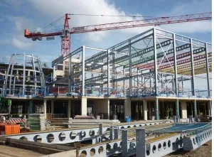
Braced steel frame
Bracing systems
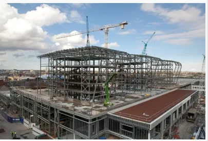
Braced steel frame under construction
In a multi-storey building , the beams and columns are generally arranged in an orthogonal pattern in both elevation and on plan. In a braced frame building, the resistance to horizontal forces is provided by two orthogonal bracing systems:
Vertical bracing. Bracing in vertical planes (between lines of columns) provides load paths to transfer horizontal forces to ground level and provide lateral stability.
Horizontal bracing. At each floor level, bracing in a horizontal plane, generally provided by floor plate action, provides a load path to transfer the horizontal forces (mainly from the perimeter columns, due to wind) to the planes of vertical bracing.
As a minimum, three vertical planes of bracing are needed, to provide resistance in both directions in plan and to provide resistance to torsion about a vertical axis. In practice, more than three are usually provided, for example in the locations shown diagrammatically in the figure below.
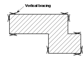
Typical arrangement of vertical bracing
Assuming that the floors act as diaphragms to provide horizontal bracing, the forces carried by each plane of vertical bracing depend on its relative stiffness and location, and on the location of the centre of pressure of the horizontal forces (see further discussion on location of vertical bracing planes, below).
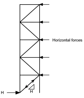
Vertical bracing, in the form of diagonal steel members, providing stability in a multi-storey building is shown in the figure below.
Stability to a building can also be provided partially or entirely by one or more reinforced concrete cores.
Location of planes of vertical bracing
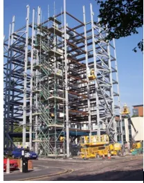
Vertical bracing in a multi-storey building
It is preferable to locate bracing at or near the extremities of the structure, in order to resist any torsional effects. See figure on the right.
Where the sets of bracing are identical or similar, it is sufficient to assume that the horizontal forces (wind loads and equivalent horizontal forces, each magnified for second order effects if necessary, see discussion below) are shared equally between the bracing systems in the orthogonal direction under consideration.
Where the stiffnesses of the vertical bracing systems differ or the bracing systems are located asymmetrically on plan, as shown in the figure below, equal sharing of forces should not be assumed. The forces carried by each bracing system can be calculated by assuming the floor is a stiff beam and the bracing systems are spring supports, as shown in the figure below.
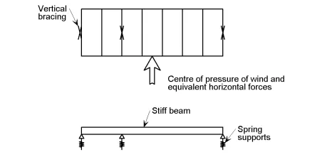
Determination of bracing forces for asymmetric arrangement of bracing
The stiffness of each bracing system should be calculated by applying horizontal forces to each bracing system and calculating the deflection. The spring stiffness (typically in mm/kN) can then be used to calculate the distribution of force to each bracing system.
Vertical bracing
In a braced multi-storey building , the planes of vertical bracing are usually provided by diagonal bracing between two lines of columns, as shown in the figure below. Either single diagonals are provided, as shown, in which case they must be designed for either tension or compression, or crossed diagonals are provided, in which case slender bracing members carrying only tension may be provided.
Cantilever truss
Note that when crossed diagonals are used and it is assumed that only the tensile diagonals provide resistance, the floor beams participate as part of the bracing system (in effect a vertical Pratt truss is created, with diagonals in tension and posts – the floor beams – in compression).
The vertical bracing must be designed to resist the forces due to the following:
· Wind loads
· Equivalent horizontal forces, representing the effect of initial imperfections
· Second order effects due to sway (if the frame is sensitive to second order effects).
Guidance on the determination of equivalent horizontal forces and on the consideration of second order effects in discussed in the sections below, and a Frame stability design tool is also available.
Forces in the individual members of the bracing system must be determined for the appropriate combinations of actions. For bracing members, design forces at ULS due to the combination where wind load is the leading action are likely to be the most onerous.
Where possible, bracing members inclined at approximately 45° are recommended. This provides an efficient system with relatively modest member forces compared to other arrangements, and means that the connection details where the bracing meets the beam/column junctions are compact. Narrow bracing systems with steeply inclined internal members will increase the sway sensitivity of the structure. Wide bracing systems will result in more stable structures.
The table below gives an indication of how maximum deflection varies with bracing layout, for a constant size of bracing cross section.
| Storey height | Bracing width | Angle from horizontal | Ratio of maximum deflection (compared to bracing at 34°) |
| h | 2h | 26° | 0.9 |
| h | 1.5h | 34° | 1.0 |
| h | h | 45° | 1.5 |
| h | 0.75h | 53° | 2.2 |
| h | 0.5h | 63° | 4.5 |
| Bracing efficiency |
Horizontal bracing
Horizontal bracing (in the roof) in a single storey building
A horizontal bracing system is needed at each floor level, to transfer horizontal forces (chiefly the forces transferred from the perimeter columns) to the planes of vertical bracing that provide resistance to horizontal forces.
There are two types of horizontal bracing system that are used in multi-storey braced frames:
· Diaphragms
· Discrete triangulated bracing.
Usually, the floor system will be sufficient to act as a diaphragm without the need for additional steel bracing. At roof level, bracing, often known as a wind girder, may be required to carry the horizontal forces at the top of the columns, if there is no diaphragm. See figure on the right.
Horizontal diaphragms
All floor solutions involving permanent formwork such as metal decking fixed by through-deck stud welding to the beams, with in-situ concrete infill, provide an excellent rigid diaphragm to carry horizontal forces to the bracing system.
Floor systems involving precast concrete planks require proper consideration to ensure adequate transfer of forces if they are to act as a diaphragm. The coefficient of friction between planks and steelwork may be as low as 0.1, and even lower if the steel is painted. This will allow the slabs to move relative to each other, and to slide over the steelwork. Grouting between the slabs will only partially overcome this problem, and for large shears, a more positive tying system will be required between the slabs and from the slabs to the steelwork.
Connection between slabs may be achieved by reinforcement in the topping. This may be mesh, or ties may be placed along both ends of a set of planks to ensure the whole floor acts as a single diaphragm. Typically, a 10 mm bar at half depth of the topping will be satisfactory.
Connection to the steelwork may be achieved by one of two methods:
· Enclose the slabs by a steel frame (on shelf angles, or specially provided constraint) and fill the gap with concrete.
· Provide ties between the topping over the planks and an in-situ topping to the steelwork (known as an ‘edge strip’). Provide the steel beam with some form of shear connectors to transfer forces between the in-situ edge strip and the steelwork.
If plan diaphragm forces are transferred to the steelwork via direct bearing (typically the slab may bear on the face of a column), the capacity of the connection should be checked. The capacity is generally limited by local crushing of the plank. In every case, the gap between the plank and the steel should be made good with in-situ concrete.
Timber floors and floors constructed from precast concreted inverted tee beams and infill blocks (often known as ‘beam and pot’ floors) are not considered to provide an adequate diaphragm without special measures.
Discrete triangulated bracing
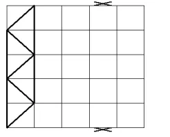
Typical floor bracing arrangement
Where diaphragm action from the floor cannot be relied upon, a horizontal system of triangulated steel bracing is recommended. A horizontal bracing system may need to be provided in each orthogonal direction.
Typically, horizontal bracing systems span between the ‘supports’, which are the locations of the vertical bracing. This arrangement often leads to a truss spanning the full width of the building, with a depth equal to the bay centres, as shown in the figure on the left.
The floor bracing is frequently arranged as a Warren truss, or as a Pratt truss, or with crossed members acting only in tension.
The effects of imperfections
Appropriate allowances need to be incorporated in the structural analysis to cover the effects of imperfections, including geometrical imperfections such as lack of verticality, lack of straightness, lack of flatness, lack of fit and any minor eccentricities present in joints of the unloaded structure.
The following imperfections should be taken into account:
· Global imperfections for frames and bracing systems
· Local imperfections for individual members.
Global imperfections may be taken into account by modelling the frame out of plumb, or by a series of equivalent horizontal forces applied to a frame modelled vertically. The latter approach is recommended.
In a braced frame with nominally pinned connections, no allowance is needed in the global analysis for local imperfections in members because they do not influence the global behaviour and are taken into account in when verifying member resistances in accordance with the design Standard.


Comments are closed