
Introduction
In the case of plane frame, all the members lie in the same plane and are interconnected by rigid joints. The internal stress resultants at a cross-section of a plane frame member consist of bending moment, shear force and an axial force. The significant deformations in the plane frame are only flexural and axial. In this lesson, the analysis of plane frame by direct stiffness matrix method is discussed. Initially, the stiffness matrix of the plane frame member is derived in its local co-ordinate axes and then it is transformed to global co-ordinate system. In the case of plane frames, members are oriented in different directions and hence before forming the global stiffness matrix it is necessary to refer all the member stiffness matrices to the same set of axes. This is achieved by transformation of forces and displacements to global co-ordinate system.
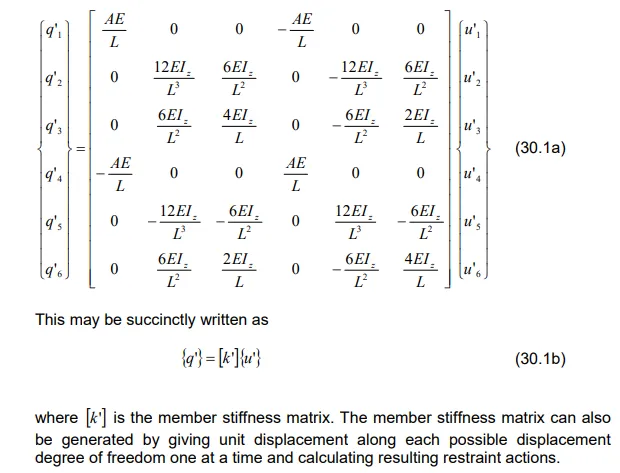
Member Stiffness Matrix
Consider a member of a plane frame as shown in Fig. 30.1a in the member coordinate system ” zyx ‘. The global orthogonal set of axes xyz is also shown in the figure. The frame lies in the xy plane. The member is assumed to have uniform flexural rigidity EI and uniform axial rigidity EA for sake of simplicity. The axial deformation of member will be considered in the analysis. The possible displacements at each node of the member are: translation in – and – direction and rotation about – axis.


Comments are closed