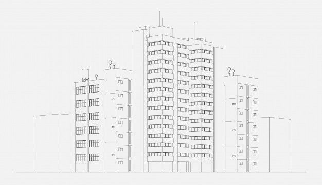
Transfer structures are often times used in tall buildings, usually for transferring high forces and loads to other structures that can resist them. For example, a transfer beam can transfer loads from stories above to stories below. Usually, transfer structures can optimize space by changing column grids between stories so that structural framing design can be flexible. We will explore the different types of transfer structures.
Transfer Plates
The construction of the transfer plates is usually considered difficult. First, the transfer floor of a structure is usually located at higher stories. Therefore, the plate is to be erected high up at higher level stories. Moreover, transfer plates are heavy (thickness is around 3m and the area can be up to 1500 m^2). This provides limited construction space and formwork options. There are several solutions:
Falsework systems, such as steel girder trusses, can act as falsework erection system AND working platform for reinforcement fixing and concreting.
1. Propping that span below 3-4 floors can be erected to support the transfer plate.
2. Post-tensioning method can be used to reduce the thickness of the plate structure and reinforcement content.
Transfer plate design is based on the slab thickness and should consider flexure and concrete crack control.
 |  |
B vs D Regions
Transfer Beams
Transfer beams transfer heavy and concentrated loads through shear. In order to avoid progressive collapse, the transfer beam should be cast monolithically and continuously while spanning over several supports. The structural system should also provide an alternative load path for load path redundancy. Moreover, for transfer beams, deflection controls. If the transfer beam deflects, all the floors above the transfer beam will deflect with it.
Transfer beam design is different from that of a main or secondary reinforced concrete beam design. This is because transfer beams have nonlinear stress distribution caused by large concentrated point loads from the column loads of the stories above. This will induce a discontinuity region due to the concentrated loads. Linear elastic theory for standard beam design cannot be used.
For transfer beam design, you can either use the deep beam method or the strut and tie model method, depending on design assumptions. We will focus on the strut and tie model. The strut and tie model designs for nonlinear stress distribution and behavior of complex members using simplified truss models.
Here is the strut and tie design process:
1. Define the framing, loads, and reactions of the structure
2. Define the B & D regions
3. Strut and tie model is based on both the St Venant’s Principle and the Bernoulli Hypothesis. B regions are based on the Bernoulli Hypothesis, where linear strains are. The beam’s flexural check can use this region’s linear elastic theory method. D regions are based on St Venant’sPrinciple. This region occurs due to discontinuity caused by concentrated loads, which leads to nonlinear stress distribution. This portion of the beam is idealized as a truss, where the members are axially loaded. FEM analysis or empirical approximations are to be used.
1. Determine the inclined angle between the strut and the tie members. This inclined angle is different and can be determined under your respective codes. Usually, the angle should be more than 25 degrees.
2. Design B regions
3. Make a STM to define stress flow in D region
4. Find member forces of the truss and design the members

Source: https://www.djc.com/
Steel Transfer Trusses
Like the strut and tie truss model, the steel transfer truss consists of axially loaded members which only transfer axial forces through pinned joints. The trusses are lighter in self-weight and can transfer loads over large spans. Parallel chord trusses, such as lattice girders or floor girders, are usually used for the transfer structure.


Comments are closed