Introduction
In this article reinforced concret beam design is described in detail with solved examples. Beam design is described more in detail in these articles: Flexural Design of Reinforced Concrete Beams, Serviceability of Reinforced Concrete Beams, and Shear Design of Reinforced Concrete Beams.
Concepts and Formulas
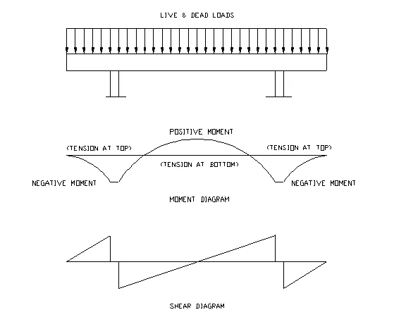
Loads (Dead & Live), bending moment, and shear diagram of a concrete beam are shown below respectively:
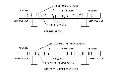
Failure modes and reinforcements
- Concrete is assumed to resist compression only, tension shall be resisted by reinforcements. Reinforcements shall be placed at the side of the beam that has tension. For a simply supported beam, tension is at the bottom of the beam while for a cantilever end, tension is at the top of the beam.
- Shear is at its maximum at the edge of supports. Diagonal shear cracks are normally developed close to the support. Stirrup for shear reinforcement is normally placed vertically to intercept the crack. They are normally closer spaced near the support and gradually spread out toward the center of the beam.
Ultimate Strength design of flexural reinforcements
Design assumption:
- Strain distribute linearly across the section.
- Concrete resists only compressive stresses.
Therefore, the stress distribution across the section of the beam is as shown below:
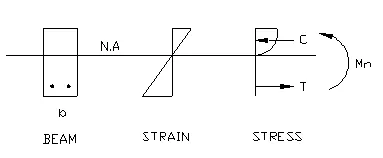
At an ultimate strain of 0.003, the stress at extreme fiber of the beam reaches ultimate strength of concrete fc’. The distribution of the compressive stresses is a complex curve. For calculation purpose, a stress block of 0.85fc’ spread over a depth, a, is used. Therefore, the total compressive stress in a rectangular beam is
C = 0.85fc’ab
Where b is the width of the beam.
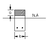
At ultimate stress situation, the concrete at top portion is subjected to compression. The compressive stresses distribute uniformly over a depth a. The resultant of compressive stress, C is located at a distance, a/2, from the top surface. The tensile force is taken by rebars at an effective distance, d, from the top surface. By equilibrium, the tensile force is equal to the compression resultant,
T = Asfy = C = 0.85f’c ab
where fy is the yield strength of reinforcing steel and As is the area of steel. Therefore,
The depth of stress block,
a = Asfy/(0.85f’c b), or a = Asfyd/(0.85f’c bd),
Let the reinforcement ratio, r = As/bd, then
a = rfyd/0.85f’c
Let m = fy/0.85f’c , then, a = rdm..The nominal moment strength of the section,
Mn = C (d-a/2) = 0.85f’c ab(d-a/2)
Then, The nominal moment strength of the section,
Mn = Asfy (d-a/2) = Asfy (d-rdm/2) = Asfy d- Asfy drm/2
ACI code requires that the factored moment,
Mu £ f Mn
Where, f = 0.9, is the strength reduction factor for beam design. Let Mu = f Mn , We have Mu = f (Asfy d- Asfy drm/2)
Divide both side by bd2, we have Mu/fbd = (As/bd)fy -(As/bd) fy rm/2) = rfy – fy r2m/2)
Let Rn = Mu/fbd2, and we can rewrite the equation as
r2(m/2) – r – Rn/fy = 0
Solving the equation, the reinforcement ratio,
r = (1/m)[1-(1-2mRn/fy)1/2]
The area of reinforcement is As = rbd