
In linear algebra, a rotation matrix is a matrix that is used to perform a rotation in Euclidean space. For example, using the convention below, the matrix
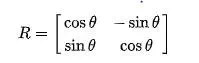
rotates points in the xy-plane counterclockwise through an angle θ about the origin of a two-dimensional Cartesian coordinate system. To perform the rotation using a rotation matrix R, the position of each point must be represented by a column vector v, containing the coordinates of the point. A rotated vector is obtained by using the matrix multiplication Rv. The examples in this article apply to active rotations of vectors counterclockwise in a right-handed coordinate system by pre-multiplication. If any one of these is changed (such as rotating axes instead of vectors, a passive transformation), then the inverse of the example matrix should be used, which coincides with its transpose.
Since matrix multiplication has no effect on the zero vector (the coordinates of the origin), rotation matrices describe rotations about the origin. Rotation matrices provide an algebraic description of such rotations, and are used extensively for computations in geometry, physics, and computer graphics. In some literature, the term rotation is generalized to include improper rotations, characterized by orthogonal matrices with determinant −1 (instead of +1). These combine proper rotations with reflections (which invert orientation). In other cases, where reflections are not being considered, the label proper may be dropped. The latter convention is followed in this article. Rotation matrices are square matrices, with real entries. More specifically, they can be characterized as orthogonal matrices with determinant 1; that is, a square matrix R is a rotation matrix if and only if RT = R−1 and det R = 1. The set of all orthogonal matrices of size n with determinant +1 forms a group known as the special orthogonal group SO(n), one example of which is the rotation group SO(3). The set of all orthogonal matrices of size n with determinant +1 or −1 forms the (general) orthogonal group O(n).
In two dimensions
In two dimensions, the standard rotation matrix has the following form,
![]()
![]() ‘ alt=”{\displaystyle R(\theta )={\begin{bmatrix}\cos \theta &-\sin \theta \\\sin \theta &\cos \theta \\\end{bmatrix}}}” class=mwe-math-fallback-image-inline aria-hidden=true>.
‘ alt=”{\displaystyle R(\theta )={\begin{bmatrix}\cos \theta &-\sin \theta \\\sin \theta &\cos \theta \\\end{bmatrix}}}” class=mwe-math-fallback-image-inline aria-hidden=true>.
This rotates column vectors by means of the following matrix multiplication,
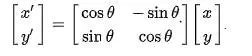
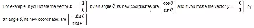
More generally, the new coordinates (x′, y′) of the point (x, y) after rotation are

![]() .
.
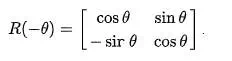
The direction of vector rotation is counterclockwise if θ is positive (e.g. 90°), and clockwise if θ is negative (e.g. −90°). Thus the clockwise rotation matrix is found as
Note that the two-dimensional case is the only non-trivial (i.e. not one-dimensional) case where the rotation matrices group is commutative, so that it does not matter in which order multiple rotations are performed. An alternative convention uses rotating axes,[1] and the above matrices also represent a rotation of the axes clockwise through an angle θ.
Non-standard orientation of the coordinate system[edit]
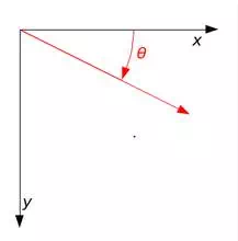
A rotation through angle θ with non-standard axes.
If a standard right-handed Cartesian coordinate system is used, with the x-axis to the right and the y-axis up, the rotation R(θ) is counterclockwise. If a left-handed Cartesian coordinate system is used, with x directed to the right but y directed down, R(θ) is clockwise. Such non-standard orientations are rarely used in mathematics but are common in 2D computer graphics, which often have the origin in the top left corner and the y-axis down the screen or page.
See below for other alternative conventions which may change the sense of the rotation produced by a rotation matrix.
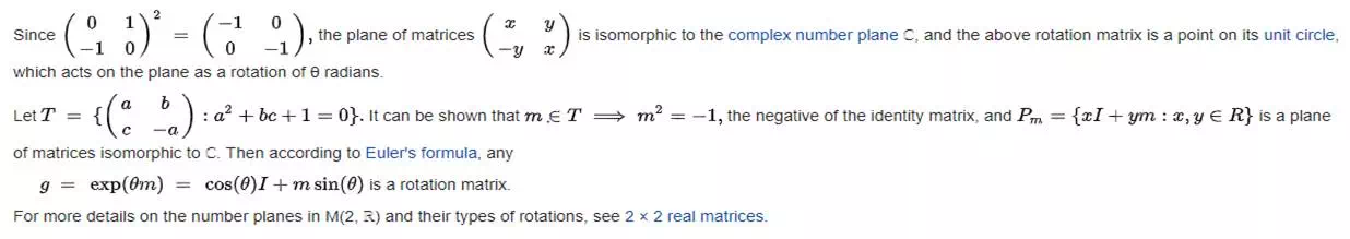
Common rotations

Complex planes in M(2, R)
In three dimensions
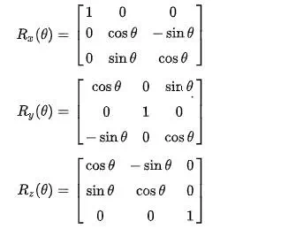
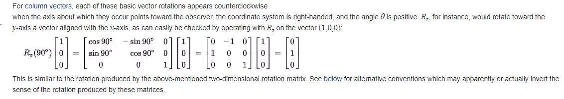
Basic rotations
A basic rotation (also called elemental rotation) is a rotation about one of the axes of a coordinate system. The following three basic rotation matrices rotate vectors by an angle θ about the x-, y-, or z-axis, in three dimensions, using the right-hand rule—which codifies their alternating signs. (The same matrices can also represent a clockwise rotation of the axes
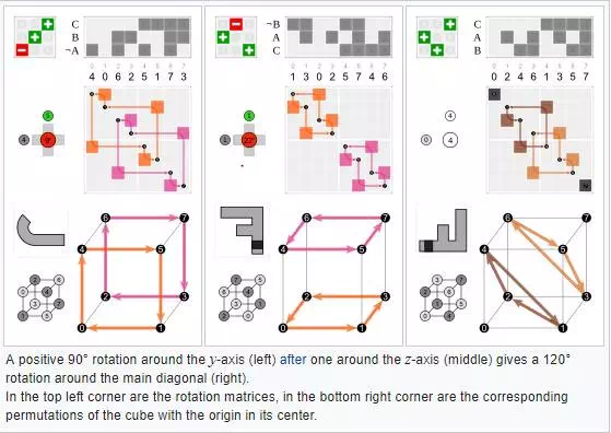
General rotations
Other rotation matrices can be obtained from these three using matrix multiplication. For example, the product
![]() ‘ alt=”{\displaystyle R=R_{z}(\alpha )\,R_{y}(\beta )\,R_{x}(\gamma )}” class=mwe-math-fallback-image-inline aria-hidden=true>
‘ alt=”{\displaystyle R=R_{z}(\alpha )\,R_{y}(\beta )\,R_{x}(\gamma )}” class=mwe-math-fallback-image-inline aria-hidden=true> ![]()
represents a rotation whose yaw, pitch, and roll angles are α, β and γ, respectively. More formally, it is an intrinsic rotation whose Tait–Bryan angles are α, β, γ, about axes z, y, x, respectively. Similarly, the product
![]() ‘ alt=”{\displaystyle R=R_{z}(\gamma )\,R_{y}(\beta )\,R_{x}(\alpha )}” class=mwe-math-fallback-image-inline aria-hidden=true>
‘ alt=”{\displaystyle R=R_{z}(\gamma )\,R_{y}(\beta )\,R_{x}(\alpha )}” class=mwe-math-fallback-image-inline aria-hidden=true> ![]()
represents an extrinsic rotation whose (improper) Euler angles are α, β, γ, about axes x, y, z.
These matrices produce the desired effect only if they are used to premultiply column vectors, and (since in general matrix multiplication is not commutative) only if they are applied in the specified order (see Ambiguities for more details).
Conversion from and to axis–angle
Every rotation in three dimensions is defined by its axis (a vector along this axis is unchanged by the rotation), and its angle — the amount of rotation about that axis (Euler rotation theorem).
There are several methods to compute the axis and angle from a rotation matrix (see also axis–angle representation). Here, we only describe the method based on the computation of the eigenvectors and eigenvalues of the rotation matrix. It is also possible to use the trace of the rotation matrix.
Determining the axis
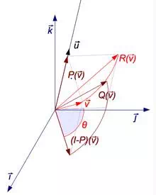
A rotation R around axis u can be decomposed using 3 endomorphisms P, (I − P), and Q (click to enlarge).
Given a 3 × 3 rotation matrix R, a vector u parallel to the rotation axis must satisfy
![]() alt=”{\displaystyle R\mathbf {u} =\mathbf {u} ,}” class=mwe-math-fallback-image-inline aria-hidden=true>
alt=”{\displaystyle R\mathbf {u} =\mathbf {u} ,}” class=mwe-math-fallback-image-inline aria-hidden=true> ![]()
since the rotation of u around the rotation axis must result in u. The equation above may be solved for u which is unique up to a scalar factor unless R = I.
Further, the equation may be rewritten

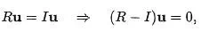
which shows that u lies in the null space of R − I.
Viewed in another way, u is an eigenvector of R corresponding to the eigenvalue λ = 1. Every rotation matrix must have this eigenvalue, the other two eigenvalues being complex conjugates of each other. It follows that a general rotation matrix in three dimensions has, up to a multiplicative constant, only one real eigenvector.
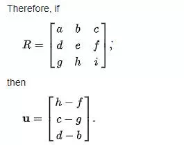
One way to determine the rotation axis is by showing that:
![]() ‘ alt=”{\displaystyle {\begin{aligned}0&=R^{\mathrm {T} }0+0\\&=R^{\mathrm {T} }(R-I)\mathbf {u} +(R-I)\mathbf {u} \\&=\left(R^{\mathrm {T} }R-R^{\mathrm {T} }+R-I\right)\mathbf {u} \\&=\left(I-R^{\mathrm {T} }+R-I\right)\mathbf {u} \\&=\left(R-R^{\mathrm {T} }\right)\mathbf {u} \,\end{aligned}}}” class=mwe-math-fallback-image-inline aria-hidden=true>
‘ alt=”{\displaystyle {\begin{aligned}0&=R^{\mathrm {T} }0+0\\&=R^{\mathrm {T} }(R-I)\mathbf {u} +(R-I)\mathbf {u} \\&=\left(R^{\mathrm {T} }R-R^{\mathrm {T} }+R-I\right)\mathbf {u} \\&=\left(I-R^{\mathrm {T} }+R-I\right)\mathbf {u} \\&=\left(R-R^{\mathrm {T} }\right)\mathbf {u} \,\end{aligned}}}” class=mwe-math-fallback-image-inline aria-hidden=true> 
Since (R − RT) is a skew-symmetric matrix, we can choose u such that
![]() alt=”{\displaystyle [\mathbf {u} ]_{\times }=\left(R-R^{\mathrm {T} }\right).}” class=mwe-math-fallback-image-inline aria-hidden=true>
alt=”{\displaystyle [\mathbf {u} ]_{\times }=\left(R-R^{\mathrm {T} }\right).}” class=mwe-math-fallback-image-inline aria-hidden=true> ![]()
The matrix–vector product becomes a cross product of a vector with itself, ensuring that the result is zero:
![]() ‘ alt=”{\displaystyle \left(R-R^{\mathrm {T} }\right)\mathbf {u} =[\mathbf {u} ]_{\times }\mathbf {u} =\mathbf {u} \times \mathbf {u} =0\,}” class=mwe-math-fallback-image-inline aria-hidden=true>
‘ alt=”{\displaystyle \left(R-R^{\mathrm {T} }\right)\mathbf {u} =[\mathbf {u} ]_{\times }\mathbf {u} =\mathbf {u} \times \mathbf {u} =0\,}” class=mwe-math-fallback-image-inline aria-hidden=true> ![]()
The magnitude of u computed this way is ||u|| = 2 sin θ, where θ is the angle of rotation.
Note that this does not work if ![]() alt=R class=mwe-math-fallback-image-inline aria-hidden=true> is symmetric. Above, if
alt=R class=mwe-math-fallback-image-inline aria-hidden=true> is symmetric. Above, if ![]() is zero, then all subsequent steps are invalid. In this case, it is necessary to diagonalize
is zero, then all subsequent steps are invalid. In this case, it is necessary to diagonalize ![]() ‘ alt=R class=mwe-math-fallback-image-inline aria-hidden=true> and find the eigenvector corresponding to an eigenvalue of 1.
‘ alt=R class=mwe-math-fallback-image-inline aria-hidden=true> and find the eigenvector corresponding to an eigenvalue of 1.
Determining the angle
To find the angle of a rotation, once the axis of the rotation is known, select a vector v perpendicular to the axis. Then the angle of the rotation is the angle between v and Rv.
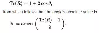
A more direct method, however, is to simply calculate the trace, i.e., the sum of the diagonal elements of the rotation matrix. Care should be taken to select the right sign for the angle θ to match the chosen axis:
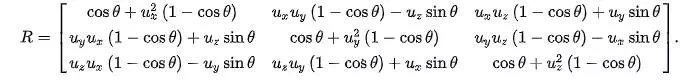
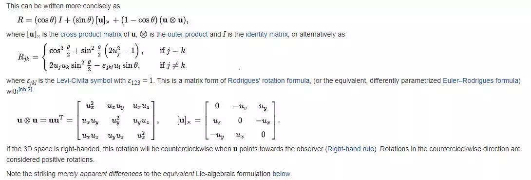
Rotation matrix from axis and angle

of θ about an axis in the direction of u is
A derivation of this matrix from first principles can be found in section 9.2 here.[4] The basic idea to derive this matrix is dividing the problem into few known simple steps.
1. First rotate the given axis and the point such that the axis lies in one of the coordinate planes (xy, yz or zx)
2. Then rotate the given axis and the point such that the axis is aligned with one of the two coordinate axes for that particular coordinate plane(x, y or z)
3. Use one of the fundamental rotation matrix to rotate the point depending on the coordinate axis with which the rotation axis is aligned.
4. Reverse rotate the axis-point pair such that it attains the final configuration as that was in step 2 (Undoing step 2)
5. Reverse rotate the axis-point pair which was done in step 1 (Undoing step 1)
![]() ‘ alt=”{\displaystyle |\theta |=\arccos \left({\frac {\operatorname {Tr} (R)-1}{2}}\right).}” class=mwe-math-fallback-image-inline aria-hidden=true>
‘ alt=”{\displaystyle |\theta |=\arccos \left({\frac {\operatorname {Tr} (R)-1}{2}}\right).}” class=mwe-math-fallback-image-inline aria-hidden=true>
